#Neues aus der Industrie
Time to Torque about optimisation
Article of the WordlCement November Edition
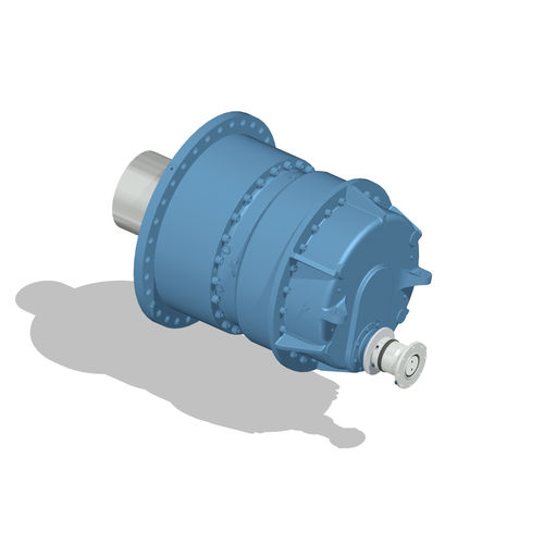
One of the core industries for Eickhoff’s industrial gearbox division is the grinding of cement and other raw materials using roller presses. Over the years, the company has built up a number of references in this area. For the reliability of the entire plant, the gearbox plays a key role. The drive, as an essential component for success with regard to plant availability, ensures the planned output quantity. The development of Eickhoff’s new ED gearbox series involved not only the incorporation of the latest scientific findings on calculation and design, but also the company’s field experience from the last 10 years. Through this, the company was able to transfer the high-quality standards from the series business in wind to its industrial gearboxes. This was made possible through the use of state-of-the-art machine tools and the consistent monitoring of material quality. Featuring 24 sizes, the new ED planetary gearbox series offers a torque range from 200 kNm up to 8000 kNm. With one to four gear stages, ratios of 4.5 – 3550 can be precisely adjusted to suit the application.
Users benefit from increased power density through optimum material utilisation and higher availability thanks to an optimised raw parts concept, without having to forego the adaptability of the equipment.
Monitoring the situation
The basis for the development of the Torque Monitoring system was the realisation that in the future, products will essentially be characterised more by their ability to be integrated into networked systems and less by technological developments in existing components, such as gears or rolling bearings. The Torque Monitor concept consistently allows the end user to easily determine the torque of their process during operation, thus optimising their system. At the same time, the user retains control over their data and the know-how of their process.
Especially in the operation of cement plants, it is important to have precise knowledge of the process parameters in order to be able to optimally match them to the material being ground. A networked drive enables the evaluation of additional parameters that provide information about the efficiency of the plant. New possibilities open up as a result, such as the early detection of running irregularities. Users can thus react quickly and reduce potential risks of machine failure to a minimum. This ensures sufficient planning of necessary repairs and reduces their scope also to a minimum.
By continuously monitoring the torque, it is also possible to adjust the input parameters so that the system can be configured to operate as efficiently as possible. This offers potential for reducing CO2 emissions and thus lowering costs. With the new ED series, Eickhoff offers the prerequisites for a new generation of networked plants that ensure optimum results with minimum energy consumption through intelligent linking and evaluation of the process-determining parameters.
In the future, every gearbox of the new series will be delivered with integrated sensors that enable continuous measurement of the speed and torque at the drive. Retrofitting of replacement gearboxes or gearboxes that are already in the field is also possible upon request.
Consisting of two strain gauge sensors, a magnet and an antenna for signal pickup, the sensor system is permanently installed in the gearbox and thus is optimally protected against the influence of harsh ambient conditions. By integrating the antenna into the bearing cover, the concept could be implemented in a very compact way.
By means of a special point welding process, the sensor package, consisting of two strain gauge sensors as well as a magnet, is firmly connected to the drive shaft and protected against corrosion by a coating. Figure 1 shows the applied shaft section of a drive shaft with the sensors. At the top of the picture is one of the two strain gauge sensors for determining torque and at the bottom is the magnet for measuring speed. The antenna is statically fixed and picks up signals from the rotating sensors. For this purpose, an induction field is built up by the copper wire embedded in the antenna. The components installed in the gearbox are oil-resistant and resistant to mechanical stress. This ensures the durability of the system.
On the side of the bearing cover, in a protected location, there is a socket for reading out the measured values. This socket is provided with IP-67 protection and prevents the ingress of coarse dirt and dust particles. Figure 2 shows the closed socket.
The socket enables a five-pin plug to be connected and serves as an interface for connecting the gearbox. A protective cover attached to the gearbox on the input side provides additional protection against mechanical stress on the socket. When delivered, the protective hood covers the socket.
Based on the label on the protective cover (Figure 3), it is possible to identify the gearboxes that are prepared for a measurement by the imprint. In addition, the QR code links to an assembly manual in which the commissioning is described in more detail.
After assembly at the factory, a functional test of the sensor system and the associated interfaces is carried out during each test run. The pre-settings of the sensor system are saved in this process step. Thus, the system can be easily put into operation if necessary. A demonstration of the setup can be seen in Figure 5.
Integration measuring system
The measuring system is set up using the measuring box, connection cables, tools and a software license. Included in the package are all necessary components to integrate the measuring system into the IT infrastructure. This realises the plug and play idea of the measuring system. As mentioned in the previous section, the measuring box can be connected to the gearbox by means of a five-pin connector. The connector is marked with the number 2 in Figure 4. The installed evaluation unit is also shown in this figure (labelled number 1).
The signal is transmitted via the five-pin socket on the bearing cover. Power is supplied via the power supply unit 100 – 240 V; 50/60 Hz; 0.45 A). Connection to the power supply is supplied via a Schuko® plug. The 12-pole plug (number 3) shown in Figure 4 is intended for this purpose. The measuring box is fastened inside the protective hood by means of the tools and screws supplied. Two threaded holes are provided in the protective hood for this connection. Thus, the protective hood not only provides additional protection for the socket, but also for the measuring box. The cable guides also allow easy laying of the cables. Connection of the measuring box to the computer or laptop is done via a USB interface and the supplied cable. The slot 4 shown in Figure 4 is provided for such a connection. Optionally, the measuring box is also supplied with an additional CAN output. This allows the measuring system to be integrated into common machine control systems. For an OEM, the advantage is that the power supply and data transmission can be done via the machine. The IP-67 compatibility of the slots as well as the connection cables is ensured even after complete cabling of the system. This means that the measuring system is ideally equipped for dusty, harsh environments.
The sampling rate of the measuring system is 2.0 kS/s. It is possible to set the measuring system to different measuring ranges. In the standard configuration, the measuring system has a measurement accuracy of ±5%, which can be improved to < ±1% by a calibration process. A higher measurement accuracy can be achieved by an additional calibration of the shafts. The graphical display of the measurement data is achieved by installing the supplied software. This is compatible with all common Windows operating systems. The speed and the torque are processed in real time and visualised by bar chart and numerical value. The measured value output takes place via an analogue or optionally also via a digital CAN interface.
Prospects
The first step in the direction of condition monitoring (CM) can be taken with the implementation of the Torque Monitoring concept.
This lays the foundation for further developments in order to bring together all the necessary parameters that enable the operator to optimise their process and provide planning security for the core component of the transmission.